Our design process

How does Light Art Vision innovate?

With many years of design experience in hardware and firmware development of embedded systems, we innovate for world class organizations. We have a strong affinity for turning ideas into prototypes and cost effective, producible products. Our versatile skill base includes international standardization & compliance requirements for Industrial, Medical-, Apace & Aviation and Defense.

Our core competences are:

  • Medical Devices, IEC 60601-1 complience
  • Sensor Systems, Test & Measurement Equipment
  • RF / Wireless / Antennas / Transponder / EMC
  • Spectroscopy / Bio-Signal sensing
  • Ultra High Speed Magnetic Bearing Drives
  • Battery Chemistry Analyzers
  • Ultra Low Power Devices and Power Path Management
  • Web/IP enabled devices, Web Interfaces, IoT


We love to work with Open Source Software


And we mainly use:


QUCS


Geany


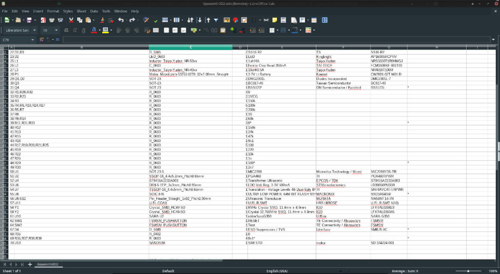
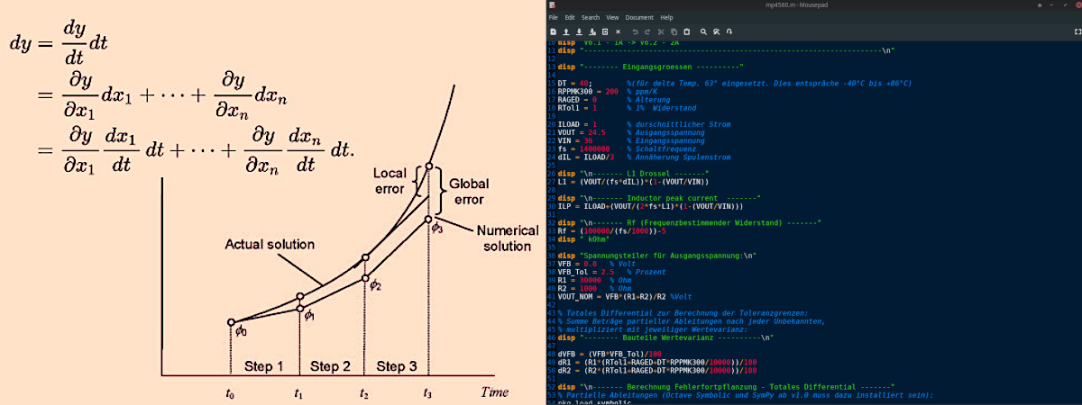
Feasibility studies, tolerance calculations, thermal modeling & simulations, validation and reliability documentation are our daily tasks.

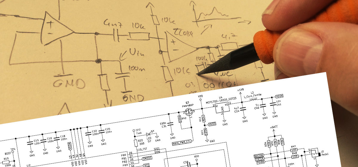
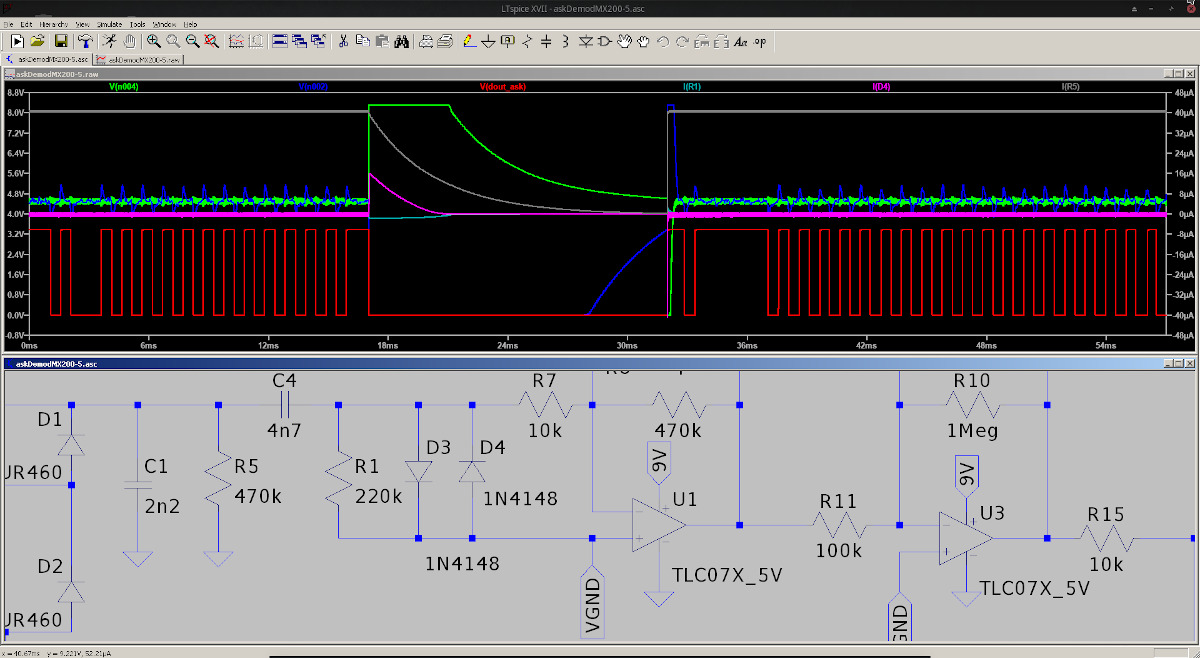
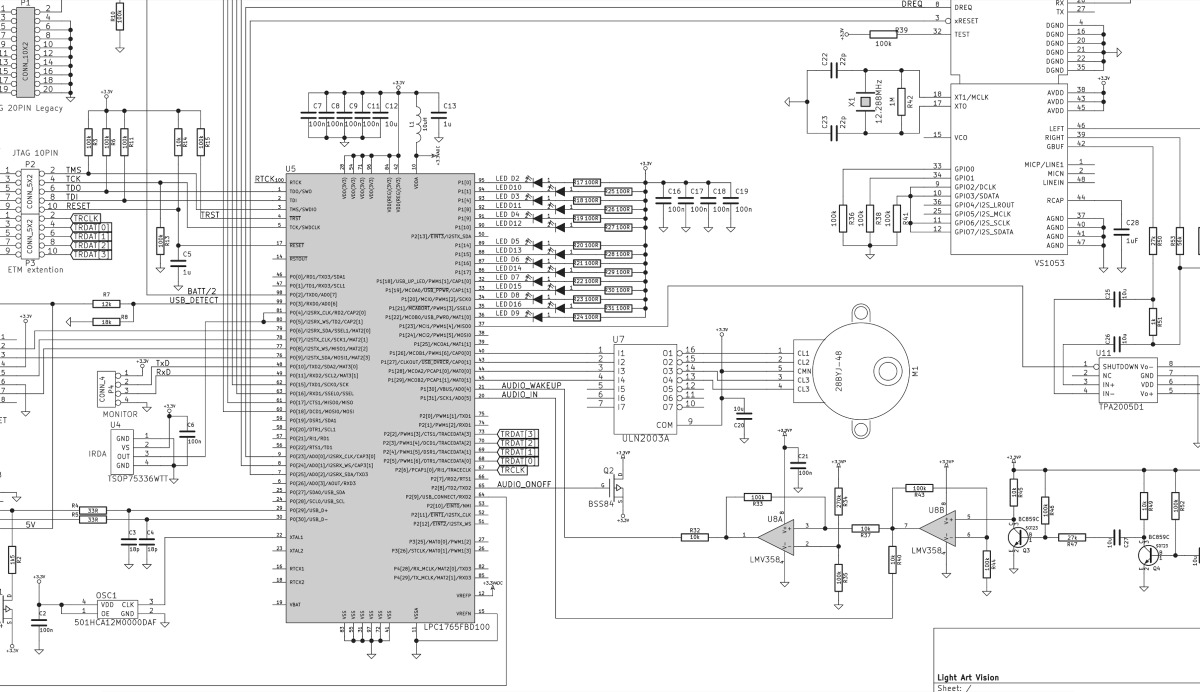
Analog Circuit Design

Resistors, capacitors, inductors, bipolar junction transistors, MOSFETs, operational amplifiers and comparators are the most common components in analog circuits. Before we evaluate specific Integrated Circuits for new designs, we always evaluate, if simple, low expensive common discrete components would fill the purpose. Therefore, availability is maximized and costs minimized in most cases.


Circuit Simulations

A good start for new circuit ideas is a simulation. We mainly use LTSPICE, but also work with Octave, Matlab Simulink, QUCs, Microwave Office, Ansoft HFSS and more. Circuit Simulations give a good feedback if your circuit idea is feasible and also let you optimize components, parameters and values. Even power consumption and thermal behavior can be simulated.


Theory is not always reality. Proof of concept

Often, a circuit simulates very well, but doesn’t work at all in real life. To avoid unnecessary PCB Layouts and Proto Boards, which safe a lot of money, we put parts of the design on a spread board to test and measure. Only if the circuit behaves like expected, we go ahead with the development.


Embedded Systems

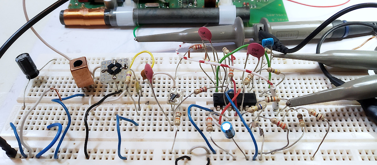
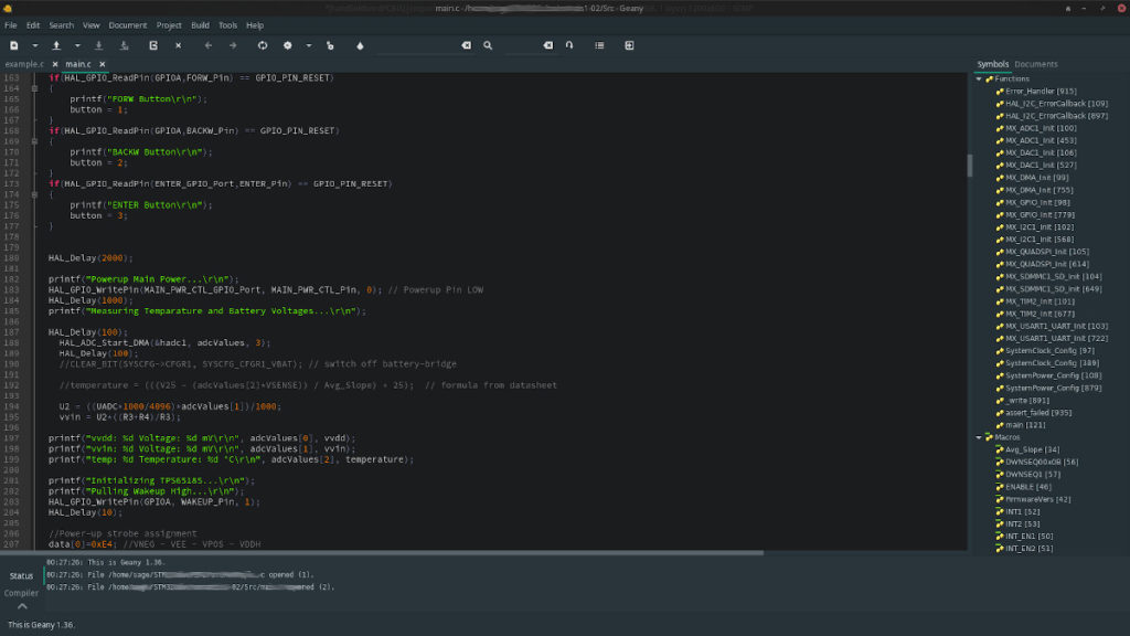
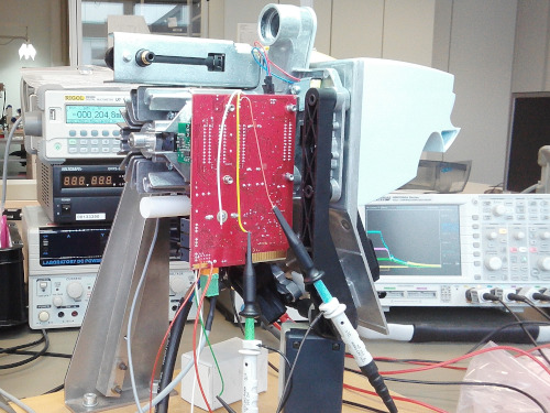
If an embedded System is part of the design (which in most cases is), many tests can be done with an evaluation board of the desired Microcontroller. PWMs, ADCs, Interrupts, Capture Compare, DACs or just GPIOs can be evaluated and basic functionality confirmed. Most Eva-Boards have a programmer on board.


Test & Measurment

Test and measurements are always a major part of the design engineering process of electronic circuits and embedded systems. Timings have to be met, Voltage levels need to be where they are expected and signals should have the right frequency. We mainly work with Teledyne leCroy, but also use Tektronix and Rigol Oscilloscopes.


Schematic Capture

With most of the design functionality simulated, tested and evaluated, the actual Schematic can be drawn. This is usually done with an EDA (Electronic Design Automation) Software. We prefer to use KiCAD. But we are also working with Eagle, Zukem CR8000, Altium, Pads, Cadence and Mentor Graphics.


PCB Layout


With a finished Schematics, the Layout of th
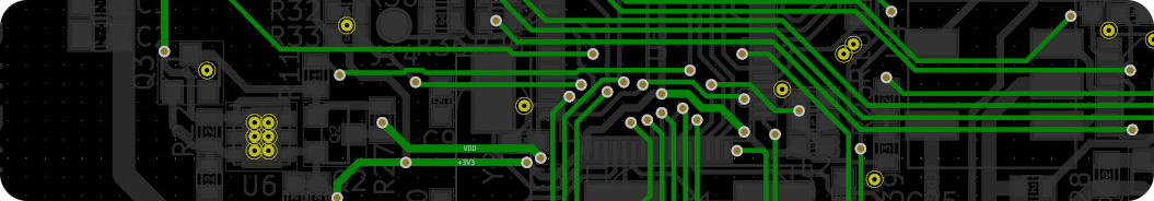
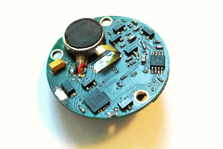
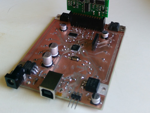
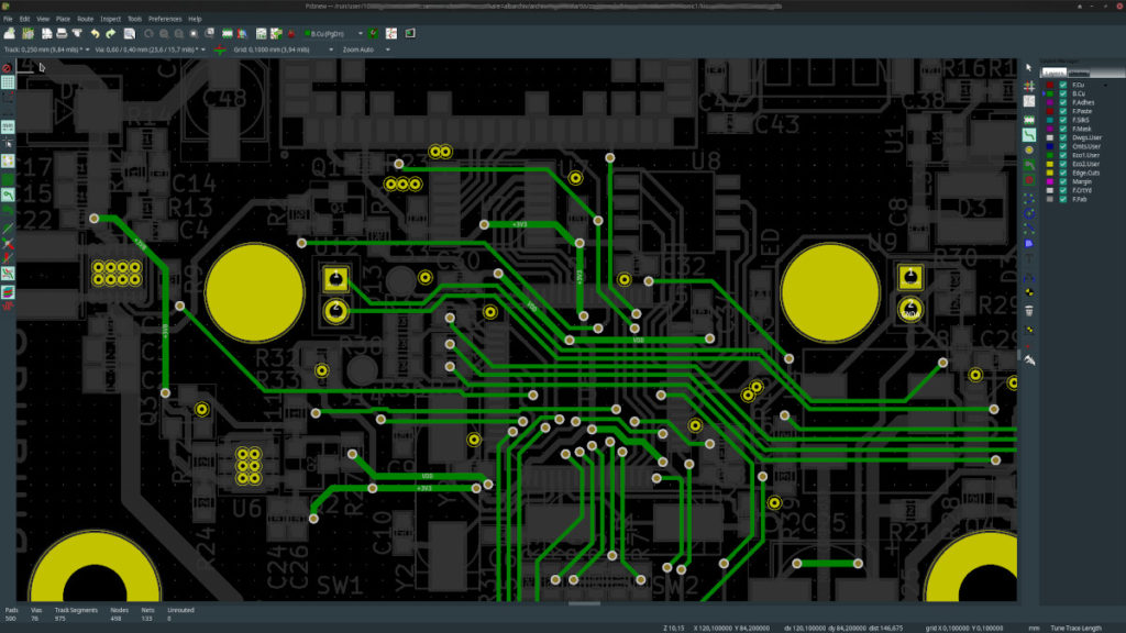
e PCB Board is most likely the next step in the design process. Good Layouts meet all the power requirements while optimized for EMC (Electromagnetic Compatibility) and Signal Integrity. We have many years of such board design experience.


Bill Of Material, supplier identification and purchasing

Once the schematics is captured and the layout is done, its a good time to generate a BOM (Bill of Material) for production costs and component availability evaluation. Component Distributors are now able to quote. Samples can be ordered. Fabrication Instructions prepared.


Rapid PCB prototyping

If there is too much excitement to wait for a PCB Service to have a Proto PCB made, which usually takes 3-5 working days, we use our PCB CNC milling machine running LinuxCNC to have the board done instantly. This also may safe weeks if multiple design iterations have to be done.


Hand soldering

After cleaning up the freshly made Proto PCB from small particles of copper leftovers, the components are being hand soldered onto the board. To reach the best soldering results, this is performed underneath a lab microscope.


PCBA professionally made PCBs and automated assembly

Alternatively to the hand soldering, if there a couple of days can be invested for prototyping, a professionally made PCB can be made with components assembled automatically.


Firmware development

Once a peace of electronic hardware is built, the firmware can be programmed (in case the project has an embedded system and contains a microcontroller). Firmware programming often is the most time consuming task of an embedded systems project. We mostly use the GCC compiler and Linux based Tool-chains, preferable on the command line for Bare Metal C Firmware development.


Tolerance and error calculations

After basic circuit functionality testing, a manual tolerance calculation is mandatory for most critical parts of the electronic circuit. We use the Chain Rule with Total Differentials and perform those calculations with Octave or Matlab. If a product fails and causes damage, only clear and comprehensible mathematical solutions are valid proof of a correct design in case of an investigation.


Validation testing of all operating states under all conditions

Tests of all possible operating states of the newly developed device can be done at this stage. If necessary, some of the tests have to be performed in temperature- or environmental chambers. The test results are being compared with the results of the tolerance calculation and clearly documented.


EMC tests and certifications


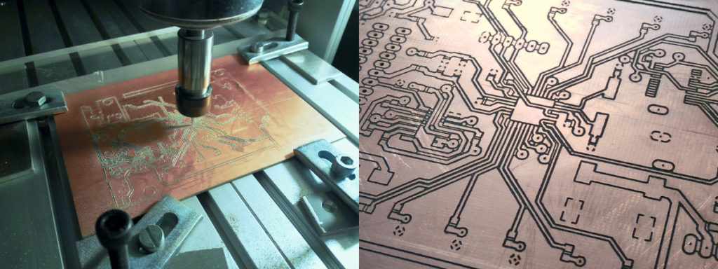
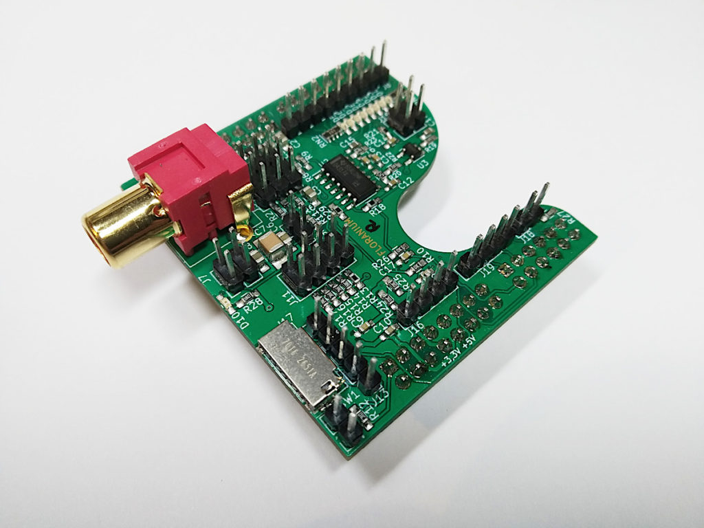
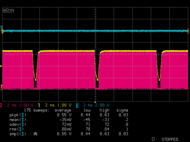
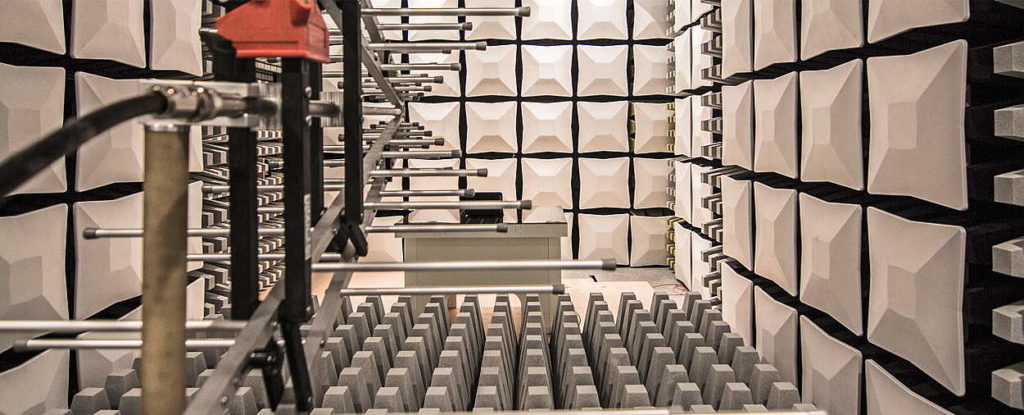
When all test results are nominal, a second prototyping phase can be started with more than just one PCB for field tests. EMC tests and certifications will be performed at this time. Clear documentation of all test results are a must. If a product fails some time later when in use, possible causes can be found in this documentation.


3D Modeling and photo-realistic rendering

For consumer and many other products, it is helpful, if an image of the final product can be rendered  before the actual product is built. This helps during the engineering and development process to evaluate the user experience and modify hardware, schematics and firmware accordingly. We use Blender to provide photo-realistic product views and animations.


Let us know about your ideas, projects and requirements!

We are more than happy to share our knowledge, support, develop, build, train, teach and consult.

Book a workshop