
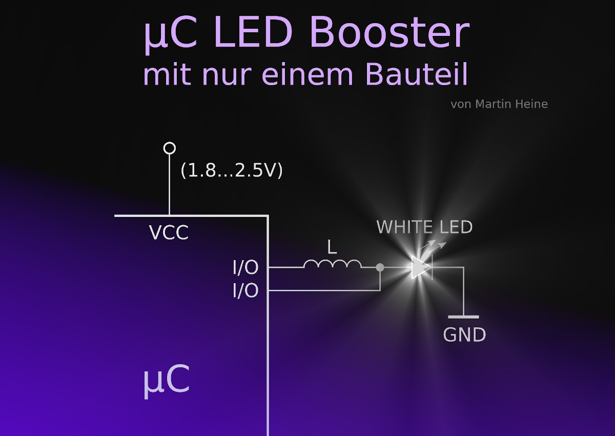
Imagine ou like to connect a white LED to a microcontroller operating from a 3 V supply voltage. Unfortunately, this doesn’t work and your nice white LED only lights up feebly or not at all.

Why does it work perfectly with red and green LEDs , but not with white?
A bit of data sheet research reveals the reason: white LEDs have a forward voltage of 3.2 V, so a 3 V supply is simply not enough to let them light up properly. The advice you often see in online forums is to use a boost converter to generate a higher voltage, along with a transistor switch to control the LED. For just a single LED, this seems like a lot of overhead.
The good news is that th ere’s an easier way. And it only needs one inexpensive component: an inductor, which costs next to nothing. If you wire it up right and drive it the
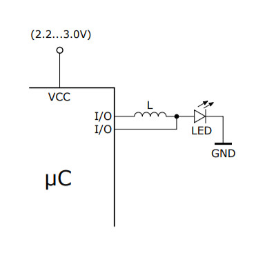
right way , your white LED will light up nicely — and this even works with a microcontroller supply voltage as low as 2.5 V. Magic? Not at all.
The circuit shown in Figure 1 is a boost converter. It also goes by other names, such as step-up converter. But how does this minimalistic boost converter work?
Operating principle of a boost converter
Take an inductor L (a coil) and connect one end to the input voltage UIN and the other end to a switch S tied to ground. When the switch S is closed, a gradually rising current flows through the inductor L, creating a magnetic field. When the switch S is opened a bit later the magnetic field collapses, generating an inductive voltage over the coil (Figure 2), the same as an ignition coil in a car.
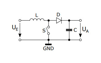
This voltage adds to the supply voltage, so the voltage UOUT (UA in the drawing) )at the diode D (which charges the capacitor C) is higher than the supply voltage. When the switch S is closed again, this process repeats. A LED is basically just a diode, so the diode D can be replaced by a LED (Figure 3). And the LED can be connected directly to ground.